
Your current location is:Home>>Product Center
Product Center
-
High frequency transformer series
-
Magnetic ring
-
I-shaped inductance
-
Magnet inductance
-
Magnetic beads
-
common mode choke
-
Air core coil
-
Color ring inductor
-
Chip inductor series
-
Mid-circle coil
-
Low frequency power transformer
-
Charging power
E-mail: fengcl@126.com
product name:photobank
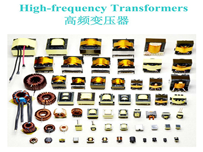
Product introduction: The high-frequency Transformer is a power transformer whose operating frequency exceeds the intermediate frequency(10kHz). It is mainly used as a high-frequency switching power supply Transformer in high-frequency switching power supplies, and also for high-frequency inverter power supplies and high-frequency inverter welding machines. According to the operating frequency, it can be divided into several grades: 10kHz -50kHz, 50kHz -100kHz, 100kHz ~ 500kHz, 500kHz ~ 1MHz, 10MHz or more.
The high frequency Transformer is the most important part of the switch power supply. There are many topologies in the switch power supply. For example, a half-bridge power conversion circuit, when working, two switch transistors turn on and off to generate a 100kHz high-frequency pulse wave, and then vary the voltage through a high-frequency Transformer, output alternating current, and the ratio of the turns of each winding coil of a high-frequency Transformer. It determines how much the output voltage is. The most prominent of the typical half-bridge variable-voltage circuits are the three high-frequency Transformers: the main Transformer, the drive Transformer, and the auxiliary Transformer(standby transformer). Each Transformer has its own measurement criteria in national regulations, such as the main Transformer., As long as it is a power supply above 200W, its core diameter(height) must not be less than 35mm. The auxiliary Transformer, when the power supply does not exceed 300W, its magnetic core diameter reaches 16mm.
operating principle
A transformer is a device that converts AC voltage, current, and impedance. When an AC current is passed through the primary coil, an AC flux is generated in the core(or core) so that the voltage(or current) is induced in the secondary coil.
The transformer consists of an iron core(or magnetic core) and a coil. The coil has two or more windings. The windings of the connected power supply are called primary coils, and the remaining windings are called secondary coils.
Design principles
In the high frequency Transformer design, the leakage inductance and distributed capacitance of the transformer must be reduced to a minimum, because the high frequency Transformer in the switching power supply transmits high frequency pulse square wave signals. In the transient process of transmission, leakage inductance and distributed capacitance can cause surge current and peak voltage, as well as top oscillation, resulting in increased loss. Usually the leakage sensitivity of the Transformer is controlled by 1 % to 3 % of the primary inductance.
Leakage inductance of primary coil-The leakage inductance of the Transformer is due to the fact that the flux between the primary coil and the secondary coil, between layers, and between turns and turns is not fully coupled.
Distributed capacitance-The capacitance formed between the winding turns of the transformer, between the upper and lower layers of the same winding, between different windings, and between the winding and the shielding layer is called distributed capacitance.
Primary winding-The primary winding should be placed in the innermost layer, so that the length of each winding of the primary winding of the transformer can be kept to a minimum, thus minimizing the use of the entire winding, which effectively reduces the distribution capacitance of the primary winding itself.
Secondary winding -- the primary winding is finished, and the secondary winding must be made by winding(3 ~ 5) layer insulation liner. This can reduce the capacitance of the distributed capacitance between the primary winding and the secondary winding, and also increase the insulation strength between the primary and secondary winding, which meets the requirements of insulation resistance.
Bias winding-whether the bias winding is wound between the primary and secondary or the outermost, depending on whether the adjustment of the switching power supply is based on the secondary or primary voltage. [ 1]
use
The high-frequency Transformer is a power transformer whose operating frequency exceeds the intermediate frequency(10kHz). It is mainly used as a high-frequency switching power supply Transformer in high-frequency switching power supplies, and also for high-frequency inverter power supplies and high-frequency inverter welding machines. According to the operating frequency, it can be divided into several grades: 10kHz -50kHz, 50kHz -100kHz, 100kHz ~ 500kHz, 500kHz ~ 1MHz, 1MHz or more. In the case of relatively large transmission power, power devices generally use IGBTs. Because IGBTs have a cut-off current trailing phenomenon, the operating frequency is relatively low; If the transmission power is relatively small, MOSFET can be used, and the operating frequency is relatively high.
Manufacturing process
One of the main points of manufacture process of high frequency Transformer:
winding
A Determines BOBBIN parameters
B All winding requirements are flat and non-overlapping principles
C single winding lines can be monochrome lines, double winding lines must be bichromatic lines or open line immersed in tin to separate foot position, so as to avoid deviation.
D cross line must be taped away
1. Disclosed completely evenly.
2. Thick winding lines are uniform and tight
3. Maintain a safe distance between the two sides of the coil and the edge of the winding slot A, B
4. The length of the sleeve must be sufficient, with one end extending into the safety tape of the winding pipe and the other end extending out of the upper edge of BOBBIN, but not near the PIN.
5. The outermost duct tape is cut on the core combination surface, and the cutting area must be covered by the core.
6. The edge of the tape is even with the winding groove, the tape is not askew, and it is not broken.
7. Tape the underside of the line and keep the underside coil insulated.
The second key point of high frequency Transformer manufacturing process.
Twisted
A vertical BOBBIN
Rough: 0.8 φ Above winding 1 circle
Line 0.2-0 .8 φ winding 1.5 laps
Very thin line 0.2 φ winding 2-3 laps
The principle of vertical BOBBIN entanglement: The principle of not exceeding the convex point is to press as much as possible.
B Horizontal BOBBIN: About 2-3 laps, do not wrap it to the end, so as not to burn BOBBIN when soldering. If there is a width limit and the specifications are strict, use this method to press the thread to the end and weld the tin, and then cut the edge PIN. To reduce the width of the whole Transformer.
C horizontal(horizontal, BOBBIN binding method: about wrapped 2-3 laps, do not press to the end to avoid scald BOBBIN when soldering.
Note: If the product has a width limit and the specification is tight, it must be a special case when the tangling part must be cut short. At this time, the tangling must be pressed to the end as much as possible.
The key points of high frequency Transformer manufacturing process:
bush
General casing position rule:
External A: The shorter the distance between the end of the sleeve and the PIN, the better, but remember that never wrap the sleeve around the PIN will cause air welding.
B interior: a boundless wall with flat BOBBIN about 1/2 L in length
B With side walls, the sleeve must be inside the wall.
The width and material of the wall tape can not be arbitrarily replaced because the width and material of the transformer are all related to safety regulations.
Width of the wall tape: It is generally necessary to be equal to the height of the winding to prevent the copper wire from being stacked on the false wall during winding, but if it is difficult to load the core, it will sometimes be about 1/2 -3 / 4 height. However, the principle that the winding line is not stacked on a false wall.
Skills: Sometimes if the thickness of the casing can be affected by the thick access line and if it affects its thickness, it is necessary to pay special attention to the position of the sleeve, and must have a safe distance(deep into the width of the false wall).
This point must be deep into the false wall sometimes because of the large gap between the false wall or when the copper foil and the M/F are coiled, there is no obvious difference between the depth of the false wall or the online M/T. Safety rods with the same width as the M/T must be selected. Each one is measured.
Fourth, the manufacturing process of high frequency Transformers:
The principle of winding copper tablets generally has the following methods:
A circle is not connected to the lead line, head and tail must not short-circuit, there is insulation between the head and tail
B round lead wire, tape width must be greater than the width of the copper sheet,
Two lead wires for copper plates in C circle or more
D Middle extended copper sheet, three leads
Key Points of High Frequency Transformer Manufacturing Technology:
Line
1) Vertical Line Standard
A fine line, rough line must be covered by more than one circle, the line position is between the base and the third height of the convex platform(if insufficient, increase the number of rational coils)
The length of the B-line head must not exceed half of the adjacent two-foot distance and the maximum length must not exceed 1mm.
C multiple groups of lines and winding lines, thin lines on the top and can not finish one and then another.
D If there is a casing, the length of the sleeve is not less than the base
When E is grooved with different foot lines, it is wound in the same direction.
2) Horizontal line standards
A line is evenly distributed on the foot, and the line head must exceed at least half of the line foot(if it is insufficient, increase the number of cable coils to make up, but not exceed the length of the line foot)
The B thread is spiral upward from the root of the foot and at least one full circle.
The length of the C-line head must not exceed half of the adjacent two-foot distance and the maximum length must not exceed 1mm.
D multiple groups of lines and winding lines, thin lines on the top layer and can not finish one and then another.
When E is in different grooves, it can be wound in the same direction and the length of the sleeve is not lower than the base and is not close to the PIN.
Key points of manufacturing process for high frequency Transformers:
tin solder
1) After soldering, the PIN foot is smooth and smooth, without foreign matter.
2) The thread head is not higher than the bump.
3) BOBBIN is complete after soldering, with no damage and short feet.
4) Oil(flux) residue is small, no tin, no short circuit.
5) There is no damage to the tape.
6) Welding solder at least once.
7) After soldering, there can be no lateral tin tips.
Key points of manufacture process of high frequency Transformer:
combination
1) The iron core combination surface is flat and there is no skew.
2) BOBBIN, CORE, connection pin kept clean, no impurity and glue.
3) Know which direction CORE with GAP is placed.
4) EE, EI, UU-type CORE maximum skew must not be greater than 0.5 mm or 1/10 CORE width.